leave a message
If you are interested in our products and want to know more details,please leave a message here,we will reply you as soon as we can.
When designing components for heavy-gauge thermoforming (or vacuum forming), product designers and mechanical engineers often transition from injection molding or metal fabrication mentalities. However, thermoforming has its own distinct set of physical rules. Because the process starts with a pre-extruded plastic sheet that is heated and stretched over a single-sided mold, failing to account for material behavior can lead to severe thinning, webbing, or parts getting stuck in the mold.
To ensure your custom plastic enclosures, housings, and panels are structurally sound and cost-effective, this guide breaks down two of the most critical DFM (Design for Manufacturing) parameters: Draft Angles and Wall Thickness.
Unlike injection molding, which uses a closed core-and-cavity tool operating under extreme pressure, heavy-gauge thermoforming utilizes a single mold (either male/positive or female/negative) combined with a vacuum and sometimes positive air pressure.
As the heated plastic sheet is stretched over or into the mold, it undergoes significant physical stretching. Understanding how draft and thickness behave during this stretching process is the secret to a successful, manufacturable design.
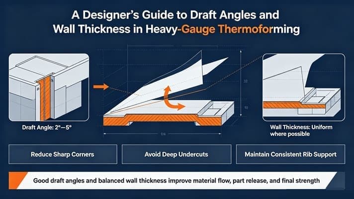
A draft angle is the taper given to vertical walls of a molded part, allowing it to be easily released from the mold. Without proper draft, a thermoformed part will lock onto a male mold as the plastic cools and shrinks, or create a vacuum lock in a female mold, making ejection difficult or impossible without damaging the part.
Key Rules for Draft Design:
One of the most common misconceptions in thermoforming design is assuming that a 5mm thick plastic sheet will yield a 5mm thick part. In reality, stretching equals thinning.
When a plastic sheet is heated and pulled into a mold, the areas that touch the mold first (or travel the furthest) experience the most stretching, resulting in thinner walls.
To optimize your heavy-gauge thermoformed parts for production, keep these golden rules in mind during the CAD design phase:
Mastering draft angles and wall thickness is essential for creating high-performance, durable plastic enclosures, machinery cowlings, and medical device housings. However, you don't have to navigate these engineering calculations alone.
At Radiant Honor Co., Ltd, our veteran tooling and engineering teams specialize in heavy-gauge thermoforming. We offer comprehensive DFM analysis for every customer project, ensuring your 3D models are optimized for perfect mold release, uniform wall thickness, and cost-effective production.
Contact our engineering team today to submit your CAD drawings for a complimentary DFM evaluation and project quotation!
Scan to Wechat :

Scan to WhatsApp :